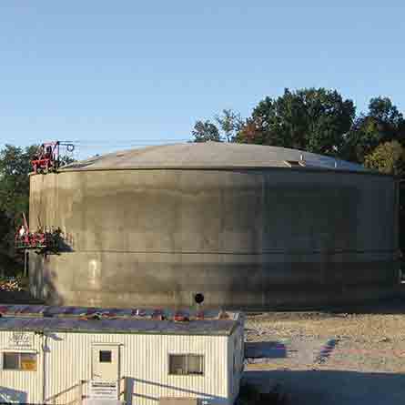
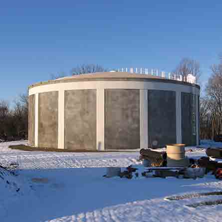
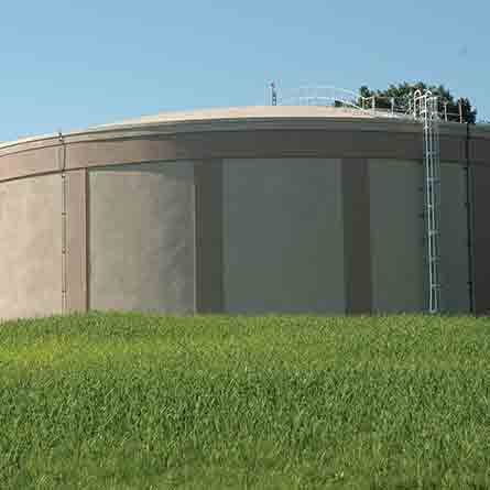
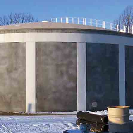
Ballenger Tank #3. Frederick County, Maryland.
The New Design Water Transmission System consists of large diameter pipelines, a 2.5 Million Gallon (MG) water storage tank, and a 15 million gallon per day (MGD) booster pumping station. WRA provided preliminary studies including hydraulic modeling, final design, contract documents, services during construction and on-site inspection for the 2.5 MG Ballenger Tank #3.
The tank is a 110-foot diameter, 35-foot high precast wire-wound prestressed concrete ground level water storage facility. Adjacent to the tank is the East County Pumping Station (designed by WRA), which pumps water to the next County pressure zone as well as the City of Frederick. Due to the location of the facilities on a ridge, design included a dedicated access road, as well as special considerations for tank and pump station appearance due to proximity to the Monocacy National Battlefield.
Services Performed
Project Highlights
Mapping/GIS/Surveying
The project required topographic surveys, boundary surveys, soil boring stakeout, cross-sections, easement plats and forest conservation easement plats. The survey was tied to the Maryland State Plane Coordinate System NAD 83 and NAVD 88 bench marks using static GPS methodology.
Geotechnical
WRA planned and monitored the test borings, prepared the geotechnical report and provided construction phase services. Project design challenges for ridge-top site included tank settlement analysis and foundation design, as well as access road alignment selection.
Electrical
Electric power was obtained at 480/277V from the local electric company. A 1250kW emergency backup diesel generator and automatic transfer switch were provided for system bacu-up. The 4000A switchboard serves four 350Hp and two 50HP pumps and a 600A Motor Control Center.
Civil/Land Development
WRA designed the access roadway to serve Ballenger Tank #3. The design accommodates the vehicles that service Tank #3. The roadway required careful design of the profile and typical section since the tank is located up a very steep hill.
Master Planning and Modeling
WRA civil engineers provided extensive planning and hydraulic modeling in order to place the water storage facility in the most ideal location. Pipe and tank sizes were checked to ensure proper flow rates and water age.
Water/Wastewater Facilities
WRA’s Construction Management and Inspection team was responsible for oversight of all transmission main, water storage facility and pumping station construction activities – five contracts in all with four being constructed concurrently.